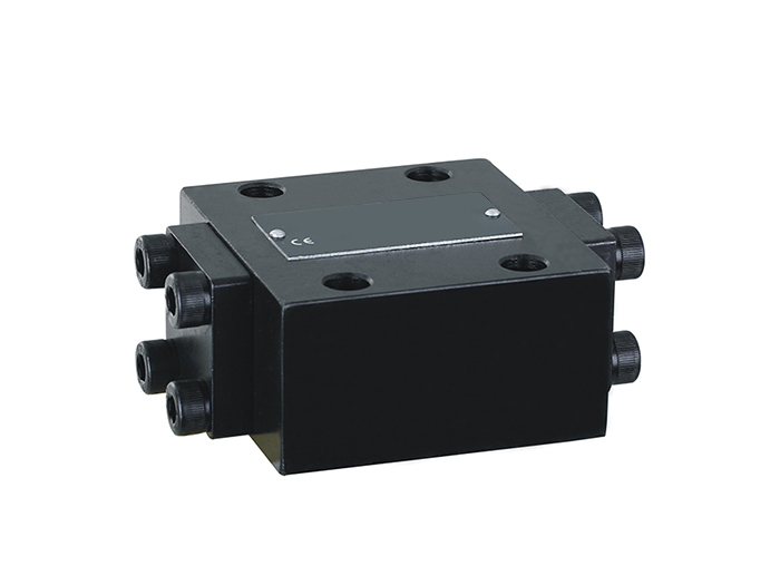
Flow Control Check Valve Overview
This Flow Control Check Valve series is designed to manage hydraulic fluid flow with optional features for pilot control, subplate mounting, and various pressure and port configurations. It provides customizable flow control to meet specific application requirements and reduces hydraulic impact with buffer and release mechanisms.
Features:
- Flow control check valve with subplate installation.
- Connection dimensions per DIN24340.
- Available with or without a drain port, as needed.
- Available with or without a pilot valve for enhanced control.
- Buffer and release pressure functionality using the pilot valve.
- Three selectable starting pressures to fit various applications.
Technical Specifications
| Parameter |
Description |
| Product Type |
Flow Control Check Valve |
| Installation |
Subplate installation |
| Drain Port Options |
V = Without drain port, L = With drain port |
| Pilot Valve Options |
A = With pilot valve, B = Without pilot valve |
| Connection Types |
P = Subplate mounting, G = Thread connection |
| Starting Pressure |
1, 2, or 3 (for adjustable starting pressures to control flow as per application needs) |
| Compatible Fluid |
No code: Mineral oil with DIN51524 or DIN51525 organic phosphate |
| Series |
30-series with specific dimensions and installation standards |
Ordering Code Breakdown
| Position |
Code |
Description |
| 1 |
S |
Flow control check valve |
| 2 |
Drain Port |
V = Without drain port, L = With drain port |
| 3 |
Oil Port Size |
SV or SL with specifications for sizes: 10, 15, 20, 25, 30 (each size has specific G and P ports) |
| 4 |
Mounting Type |
P = Subplate mounting, G = Thread connection |
| 5 |
Pilot Valve Option |
A = With pilot valve, B = Without pilot valve |
| 6 |
Series |
30-Series (30–39) |
| 7 |
Starting Pressure |
1, 2, or 3 for different pressure starting points |
Spool Symbols
| Spool Symbol |
Description |
| Symbol A |
Flow control symbol with direct flow from A to B and optional pilot flow. |
| Symbol B |
Allows for controlled flow with or without a pilot valve and reduced impact. |